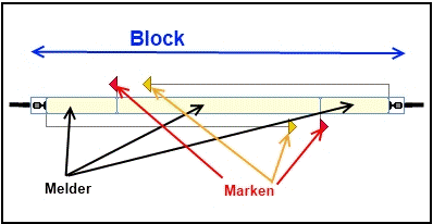
Terms: Block - Detector - Marking
Explanation of terms
In the following, the three essential basic terms block, detector and marking are explained, since it often happens that their meanings are mixed up.
Block
Blocks are the basic elements on which the tracking of train movements and the control of trains is based. A block is provided wherever locomotives or trains are to be controlled, stopped, parked or monitored. Typical examples of blocks are station tracks, shadow station tracks, sidings, block sections on open track between two stations. Further basics can be found in Chapter 5.2 Blocks and switch routes from p. 153ff.
Detectors/Contacts/Feedback
The "eyes" of the PC on the system, either permanent detectors or momentary contacts. This can be an isolated section of track on the system that detects occupancy via a current sensor or via a ground fault or a light barrier.
Relationship between block and detector/contact
For the block system to work, it is important that TrainController can track the movements of the trains running on the system and determine which blocks are occupied and which are not. The necessary feedback is generated using contact detectors (see above). To set up a block, all detectors in this block are assigned to the block. If at least one of these detector elements is switched on, the block is considered occupied. A block must therefore have at least one contact detector and can be equipped with any number of detectors. Please never equate block with detector!!
- The basics of this can be found in the aforementioned chapter 5.8 Setting up detectors in a block from p. 181ff.
Marking
The marker is used to assign a task to a detector: braking and/or stopping. For example, the braking process can be initiated exactly where the detector physically begins on the system to which a braking marker has been assigned. By specifying the so-called ramp, you can specify exactly how long the train's braking distance should be, completely independent of the speed. If, for example, the stopping point is to be somewhere else, where no detector begins, the stopping marker can be moved far enough behind the beginning of a detector using the distance until the desired stopping point is reached. This is also illustrated with several illustrations from page 185 onwards.
The (real) detector is therefore the reference for the marking: The detector is triggered and TC calculates, based on a distance-time calculation, when the corresponding marking is activated and the task associated with this marking is carried out. The prerequisite for the most accurate calculation of the distance and the ramp is of course - as you probably already guessed - the precise measurement of the locomotive!
- Further basic information on the markings can be found in chapter 5.7 Stop, brake, speed and action markings.
- Description of the markings; their colors and their functions
Differences
Block is not equal to detector is not equal to marker.
- a block must always contain at least one detector (exceptions are possible in very specific special cases).
- a block can contain more than one detector.
- a detector is usually a reference point for one or more markings.
The task of a detector is determined by its markings, whereby a detector can be assigned several tasks.
- The markings can be moved by means of distances from the physical location of a detector.
Weblinks
- TC-wiki: Momentary detector or permanent detector; a comparison
- TC-wiki: Markings; their colors and their functions
- --Digi thomas2003 (Diskussion) 15:19, 3. Jan. 2014 (CET)
- bearbeitet: --Digi thomas2003 (Diskussion) 15:19, 18. Mär. 2021 (CET), Uslex (Diskussion) 15:52, 25. Feb. 2024 (UTC), Francis1954 23:43, 11. Jan. 2025 (UTC)

